 Schematic Drawing
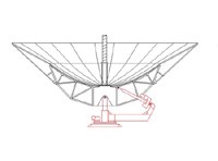
Schematic Drawing of the GEM dish with 408 MHz backfire antenna.
The GEM dis (primary mirror) is approximately parabolic. The measured shape for the primary is contained in this table:
| Radius (cm) | Height (cm) | Check |
|---|---|---|
| 0 | 0 | Definition |
| 102.87 | 15.24 | |
| 153.67 | 33.655 | |
| 204.47 | 60.325 | |
| 280.67 | 107.95 |
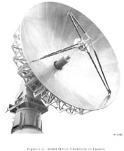
The core dish was made by Scientific Atlanta. It is a Model 8101-5.5 Earth Station Antenna designed for 12 through 14 GHz satellite ground station. The estimated surface tolerance is 0.071 cm (0.028 inches).
The halo extension panels generally extend the dish surface with tangent (continuing angle) planes as shown in the first schematic drawing in the 408 MHz configuration.
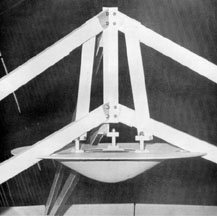
An idea of the mechanical configuration of the secondary support is
in the following figure though the actual secondary looks somewhat
different.

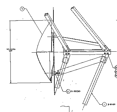
The mechanical assembly appears in the next sketch.
The 2.3 GHz receiver and feed mount directly from this same location.

The usual secondary is a Model 8181S-5.5. subreflector. The subreflector has a diamter of 58.4 cm. The raw data and corrected data in inches for the subreflector shape is in the following Text format OR MacBinary II or BinHex or Raw Data MacIntosh Excel 4.0 file.
Return to the Smoot Group page for a complete description of Dr. Smoot's group's research activities.