RAND


Photos and Conceptual Designs.
Click here to return to the Main Menu.
Radio Array Detection of Neutrinos (RAND) is a concept for detecting ultra-high energy (>1 TeV) neutrinos interacting in the Antarctica Ice Cap. Radio detection is expected to be the most effective method of detecting neutrinos at PeV energies.
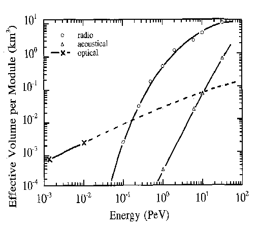
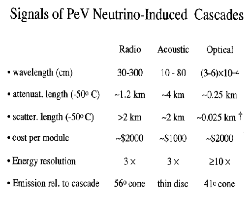
A comparison of techniques has been summarized by Dr. P. Buford Price as indicated below:
neutrino detection comparison plot

and
neutrino detection comparison table
 .
.
Since the ice is very cold (typically -50 C) and very pure, it is very transparent to long wavelength radio wave. For wavelengths longer than 30 cm the typical absorption length is a kilometer or longer. This means a single detector module can observe a large volume. Multiple detectors are required in order to obtain coincidence. A radio detector is able to observe so large a volume as to run out of ice in the upward direction or into warmer ice in the downward direction.
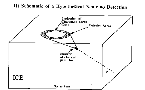
The Radio Detection Principle is based upon utilizing the Cerenkov radiation from the charged particles produced by a neutrino interaction in the ice.
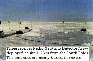
The Smoot Group has performed two preliminary tests of the feasibility of using the Antarctic Ice for radio detection in trips to the South Pole in 1989 and 1991-1992. The December 1991 - January 1992 expedition, under the acronym A.R.C.N.O. (Antarctic Radio Cherenkov Neutrino Observatory), utilized three broad-band receivers singly and in coincidence on the surface. These tests indicated that there was no insurmountable background to the radio detection. However, a surface array is not optimal for radio detector, as the earth is fairly opaque to very ultra-high energies and total internal reflection in the top layer of ice both limit the available observation solid angle. See the schematic below:

Additional study has developed the concept of an in-ice radio array neutrino detector (RAND). The deployment of the AMANDA phototube array has opened the possiblity of actual development. The AMANDA project uses phototubes to detect the Cerenkov light from muons passing relatively near the phototubes. High-energy, and thus long range muons are produced in some muon-neutrino interactions in the ice or rock below the ice. The two approaches, radio and phototube, are complementary in that they cover different but overlapping energy ranges. The Smoot Group is making an effort to put a test set of radio receivers into the Antarctic ice during the next AMANDA deployment.
The RAND group is continuing work on the theoretical and instrumental project in concert with the km^3 (cubic kilomenter) neutrino detector working group. Much of the theoretical and Monte Carlo simulation work is being done by George Frichter and John Ralston at the University of Kansas and Frances Halzen's group at the University of Wisconsin.
a) Limits or detection of very massive WIMP annihilation (neutrino channel must be there) at masses not accessible by accelerators or other ground-based experiments.
b) Neutrino oscillation in the very low neutrino mass range
c) Test of ultra-high energy cross-sections which tests the saturation of the total number of quarks and "sea" quarks in nucleons.
Click here to return to the Main Menu.
As a summer student assistant, Chris Baker, has been working on RAND with the Smoot Group. He spent most of his time attempting to redesign the antenna/receiver modules from the surface experiment so that they would be suitable for travelling down the bore holes deep into the Antarctic ice and performing radio measurements under those extreme conditions. The temperature is about -50 degrees Celsius and the pressure can be greater than 100 atmospheres. Additionally, the units must be durable to handle the turbulent submersion process.
The majority of his work can be divided into two categories: Antennas and Receivers.
Until now, general consensus was that the optimal antenna to perform these radio measurements was a biconical antenna. Its advantages are that its field pattern is symmetrical in the horizontal plane and that, due to the torroidial shape of this pattern (see the field patterns section), the field pattern along its axis of symmetry is negligible (see illustration below). This was convenient because the plan was to attach this antenna around the AMANDA string's power cables and mount the receiver inside the conical inner structure.
We then saw that the biconical design had a few limitations. First of all, it would need to be enclosed in some sort of protective container, to prevent it from being deformed by the rushing water currents during submersion. The biconical alone is not hydrodynamic. Before pursuing this issue, we contacted several antenna engineers (see the Updates section below), who told us that the power cable through the center of the antenna was a major problem (even when insulated), s ince it passes right through the center of the field pattern. We have a possible design with a 1/4 wave choke (see illustration below), which makes the antenna blind to the center power cable. The design is quite complicated, but seems worth pursuing if the cables must run through the antenna.
Biconical Antenna with 1/4 wave choke
![]()
It was at this time that we were informed that mounting an antenna around the AMANDA cables was not acceptable from the viewpoint of the AMANDA experiment. An antenna must be designed which would not surround the cables in this way. This convinced us to explore the possibility of using an antenna which did not have the bicone structure and which would not have to encompass the cables. Without completely abandoning the bicone idea, we began to explore other options. We realized that a cylindrical antenna would behave much the same as a bicone (and even more like a standard dipole antenna). The cylindrical antenna also had the durability,structure and "ruggedness" that would be required for actual deployment. They are also simple to make. It seemed like cylindrical antennas would be the way to go. The antenna body need only be wide enough to contain the receiver and the problem is no longer "How will this antenna react when large power cables travel along its axis?", but is now, "How will the field pattern be affected by the power cable in a significant portion of it's solid angle?" It was at this time that we realized that there was no inherent reason why having a "dipole-like" antenna was necessary.
It was at this time that we stumbled across the idea of using a slotted cylindical antenna. These antennas consist of one piece of cylindrical metal, with a verical slot on one side. The feed is then bridged across the slot horizontally and an electric field is set up across the gap. Please see the illustration below. Although this is a major change in direction, this antenna performed remarkably well. The field patterns that we measured for this antenna look promising. Note that we have changed the polarization of the antenna from vertical to horizontal.
This issue of polarization has yet to be address. All of the antennas we had tested before were significantly vertically polarized. That is, an antenna would receive the greatest signal when its axis of symmetry is lined up with the E field of incoming radiation. The slotted antenna receives the greatest signal when its axis of symmetry lines up perpendicular to the E field of the incoming radiation. It is horizontally polarized. The incoming Cherenkov radiation has an electric field which is perpendicular to its direction of travel, and in the plane defined by the shower axis and the Poynting vector of the signal. Maybe the diagram below will clarify:
One can see that, although only two examples are shown, a detected signal could be located at any spot on the Cherenkov cone, so the polarization for any particular event cannot be predicted. We tried to determine whether the angle of incidence (the axis of the shower) caused a certain polarization to be preferred, but it does not appear to do so.
We measured this antenna and compared it with a standard biconical antenna. Measurements of the field patterns of both antennas show the results. We conclude that the two antennas have almost identical field patterns. The key difference, already stated, is that of polarization.
We have decided that a vertically oriented slotted cylindrical antenna is the most practical for our purposes. Here are the key reasons why:
As far as the receiver goes, we are attempting to create a way to protect the circuitry from the harsh conditions. We have explored the pressure vessel option. Although having one built is quite expensive, there is a possibility we could make a strong cylinder that would do the job. Withstanding several hundred atmospheres, however, is no small task. We are planning to operate near -50 degrees C (the temperature of the ice). The components will be similar to the receivers of the A.R.C.N.O. neutrino experiment. Click here to see a schematic of the internal circuitry. These are the actual components used for A.R.C.N.O. We are interested in making these components take up as little space as possible. Especially because a smaller pressure container is much easier to make than a large one.
There is a possibility of digitizing the signal before it is sent back up to the surface. Dave Nygren of LBNL is working on this for the AMANDA collaboration. We are definitely interested in this technology, but are assuming that we will be using traditional NIM amplification. Our experiment is not dependent on the developement of the digitizing circuitry.
Chris has written updates during his 12 weeks at LBNL this summer
to record his progress:
(Note: most of the information in them has been summarized in the sections above.)
The slotted-cylindrical antenna, although comparable to the bicone antenna in functionality, is far more advantageous. This is true from an experimental perspective. The slotted-cylinder is considerably easier to fabricate, will better withstand Antarctic conditions, does not have to enclose the receiver, and will be safer to deploy since it is narrower and more hydrodynamic.
There is still a possibility of sending a radio detector down to Antarctica this winter. It would be very advantageous to do this now. Chris Baker has done a lot of work on the antenna structure, but the receiver design and the surface equipment require further study. Chris will be returning to college at UCSB on Friday, Sept. 15. Martin Moorehead of LBNL is interested in following up Chris's work. The Smoot Group will continue exploring the viability of the radio detection of neutrinos as funding and manpower permit.
Click here to return to the Main Menu.
If you have any questions, please feel free to email Chris Baker, this page's compiler and co-author, at ubaker@mcl.ucsb.edu.
Return to the Smoot Group page for a complete description of the Smoot group's research activities.